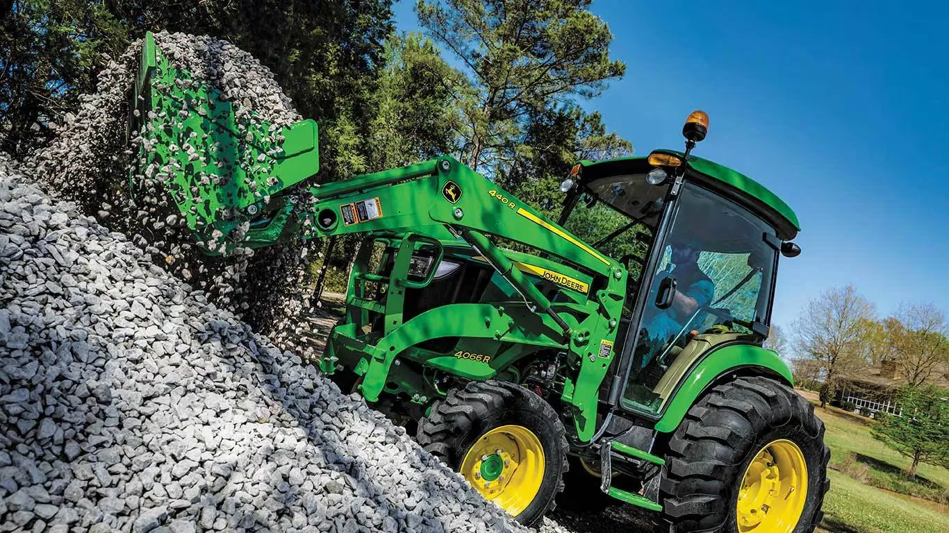
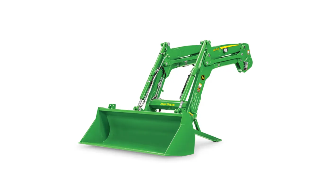
John Deere 540M Loader

Loaders
Get in Touch
  • Superior strength and visibility
  • For heavy-duty chores
  • Parking stands are integrated on the loader
Parking stands

Parking stands

#

John Deere loaders are easily removed and reinstalled on tractors without tools. The parking system allows removing or attaching the loader to the tractor in minutes without the need for tools.


To remove or park the loader, apply slight down pressure to the loader boom with the bucket dumped at approximately a 30-degree angle. With the tractor in park, lower the parking stands and place the mast pins in the open position.

Removing or parking the loader
Parking stand in stored position

Parking stand in stored position

Removing parking stand

Removing parking stand

Mast pin in the closed position

Mast pin in the closed position

Rotating mast pin to the open position

Rotating mast pin to the open position

Utilizing the boom circuit with the tractor in neutral, rotate the mast forward until the mast has rotated past the pin location on the mounting frame by extending the lift cylinder. Now using the bucket circuit, roll back the bucket until the mast is removed from the pocket and will clear the tires.

Mast pin in the open position

Mast pin in the open position

With the tractor in park, shut the engine off and relieve the hydraulic pressure as indicated for the tractor (rotating the joystick). Disconnect or open the single-point hydraulic connector (or remove couplers if no single point is installed).

Disconnect/open single-point hydraulic connection

Disconnect/open single-point hydraulic connection

Disconnect/open single-point hydraulic connections

Disconnect/open single-point hydraulic connections

Store the loader half of the single-point connector or hoses, and back away from the loader.

Single-point hydraulics disconnected

Single-point hydraulics disconnected

#
Hydraulic shut-off valve (open position)

Hydraulic shut-off valve (open position)

Hydraulic shut-off valve (closed position)

Hydraulic shut-off valve (closed position)

A hydraulic shut-off valve is included with the M & R-Series Utility & Ag Loaders to ensure the loader does not lower suddenly. For example, this allows the boom to be locked out when someone is required to be located under the loader boom for service work on the tractor. It should not be used for extended periods of time unless an appropriate support stand is also utilized.

Concealed oil lines through boom arm

Concealed oil lines through boom arm

#
Oil lines routed through the boom arm

Oil lines routed through the boom arm

Oil lines routed through the torque tube

Oil lines routed through the torque tube

Over time, increased width in tractor hoods have caused issues with available space for running traditional oil lines of a loader along the boom, making them more susceptible to damage.


To improve this situation, the oil lines have been routed through the boom arm and the torque tube, improving line protection and the appearance of the loader.

Single-point hydraulic connection on 6 Series Tractors (closed position)

Single-point hydraulic connection on 6 Series Tractors (closed position)

The H310 Loader can be ordered with a single-point hydraulic connection that also incorporates the connection point for any electrical needs. To disconnect the hydraulic connection between the loader and the tractor, it is necessary to relieve the hydraulic system oil pressure on the tractor.

Select a category to view specifications (or view all).

Key Specs

Maximum lift height (A)3578 mm 141 in.

Features

  • Lift Height: NSL: 137-141 in. (3482-3571 mm)MSL: 138-141 in. (3501-3578 mm)

Description

Loader removal (parking) made easy

Parking stands

Parking stands

#

John Deere loaders are easily removed and reinstalled on tractors without tools. The parking system allows removing or attaching the loader to the tractor in minutes without the need for tools.


To remove or park the loader, apply slight down pressure to the loader boom with the bucket dumped at approximately a 30-degree angle. With the tractor in park, lower the parking stands and place the mast pins in the open position.

Removing or parking the loader
Parking stand in stored position

Parking stand in stored position

Removing parking stand

Removing parking stand

Mast pin in the closed position

Mast pin in the closed position

Rotating mast pin to the open position

Rotating mast pin to the open position

Utilizing the boom circuit with the tractor in neutral, rotate the mast forward until the mast has rotated past the pin location on the mounting frame by extending the lift cylinder. Now using the bucket circuit, roll back the bucket until the mast is removed from the pocket and will clear the tires.

Mast pin in the open position

Mast pin in the open position

With the tractor in park, shut the engine off and relieve the hydraulic pressure as indicated for the tractor (rotating the joystick). Disconnect or open the single-point hydraulic connector (or remove couplers if no single point is installed).

Disconnect/open single-point hydraulic connection

Disconnect/open single-point hydraulic connection

Disconnect/open single-point hydraulic connections

Disconnect/open single-point hydraulic connections

Store the loader half of the single-point connector or hoses, and back away from the loader.

Single-point hydraulics disconnected

Single-point hydraulics disconnected

#

Boom lockout for easy service

Hydraulic shut-off valve (open position)

Hydraulic shut-off valve (open position)

Hydraulic shut-off valve (closed position)

Hydraulic shut-off valve (closed position)

A hydraulic shut-off valve is included with the M & R-Series Utility & Ag Loaders to ensure the loader does not lower suddenly. For example, this allows the boom to be locked out when someone is required to be located under the loader boom for service work on the tractor. It should not be used for extended periods of time unless an appropriate support stand is also utilized.

Concealed oil lines improve appearance and reduce damage

Concealed oil lines through boom arm

Concealed oil lines through boom arm

#
Oil lines routed through the boom arm

Oil lines routed through the boom arm

Oil lines routed through the torque tube

Oil lines routed through the torque tube

Over time, increased width in tractor hoods have caused issues with available space for running traditional oil lines of a loader along the boom, making them more susceptible to damage.


To improve this situation, the oil lines have been routed through the boom arm and the torque tube, improving line protection and the appearance of the loader.

Single-point hydraulic connection saves time

Single-point hydraulic connection on 6 Series Tractors (closed position)

Single-point hydraulic connection on 6 Series Tractors (closed position)

The H310 Loader can be ordered with a single-point hydraulic connection that also incorporates the connection point for any electrical needs. To disconnect the hydraulic connection between the loader and the tractor, it is necessary to relieve the hydraulic system oil pressure on the tractor.

Specifications

Key Specs

Maximum lift height (A)3578 mm 141 in.

Features

  • Lift Height: NSL: 137-141 in. (3482-3571 mm)MSL: 138-141 in. (3501-3578 mm)